
Page 6 - Durapac_2016
P. 6
sync
MASTER
SYNCHRONOUS LIFT SYSTEM WWW.DURAPAC.COM
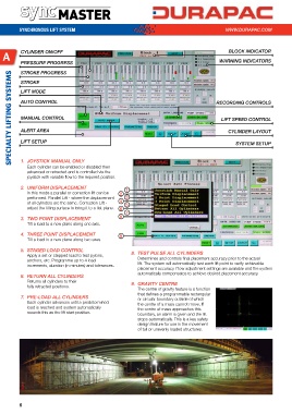
a CYLINDER ON/OFF BLOCk INDICATOR
PRESSURE PROGRESS WARNING INDICATORS
STROkE PROGRESS
SPECIALTY LIFTING SYSTEMS
STROkE
LIFT MODE
AUTO CONTROL RECORDING CONTROLS
MANUAL CONTROL LIFT SPEED CONTROL
ALERT AREA CYLINDER LAYOUT
LIFT SETUP SYSTEM SETUP
1. JOYSTICk MANUAL ONLY
Each cylinder can be enabled or disabled then
advanced or retracted and is controlled via the
joystick with variable flow to the required position.
2. UNIFORM DISPLACEMENT 1
In this mode a parallel or correction lift can be 2
performed. Parallel Lift - where the displacement 3
of all cylinders are the same. Correction Lift - 4 5
adjust the lifting surface to bring it to a flat plane. 6
7
3. TWO POINT DISPLACEMENT 8
Tilt a load to a new plane along one axis.
4. ThREE POINT DISPLACEMENT 9
Tilt a load to a new plane along two axes.
5. STAGED LOAD CONTROL
Apply a set or stepped load to test pylons, 8. TEST PULSE ALL CYLINDERS
anchors, etc. Programme up to 4 load Determines and controls final placement accuracy prior to the actual
increments, duration (in minutes) and tolerances. lift. The system will automatically test each lift point to verify achievable
placement accuracy. Flow adjustment settings are available and the system
automatically compensates to achieve desired placement accuracy.
6. RETURN ALL CYLINDERS
Returns all cylinders to their 9. GRAvITY CENTRE
fully retracted positions.
The centre of gravity feature is a function
that defines a programmable rectangular
7. PRE-LOAD ALL CYLINDERS or circular boundary outside of which
Each cylinder advances until a predetermined the centre of a mass cannot move. If
load is reached and system automatically the centre of mass approaches this
records this as the lift start position. boundary, an alarm is given and the lift
stops automatically. This is a key safety
design feature for use in the movement
of tall or unevenly loaded structures.
6